Description
New Revision D board!
The Rev D board bring useful improvements:
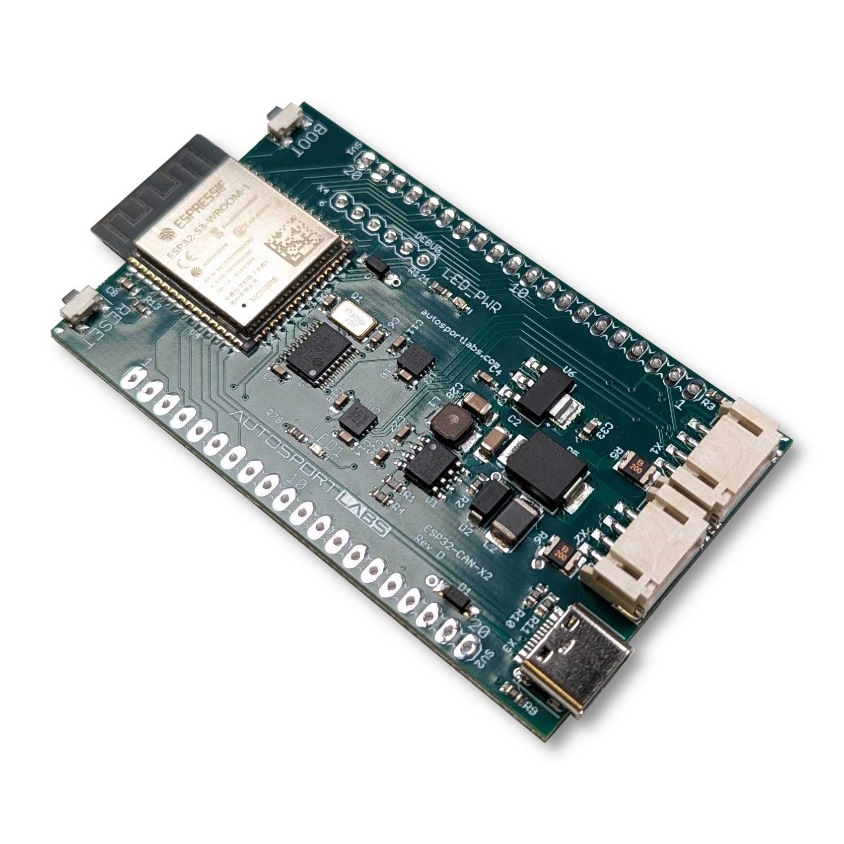
* Dual 4 pin connectors for Power + CAN connections for more convenient individual connections for each CAN bus,
* Right angle connector design that works better with the range of bolt-on accessories – makes for a lower profile design
* Boot and reset buttons are right angle for easier use when bolt-ons are mounted
Introduction
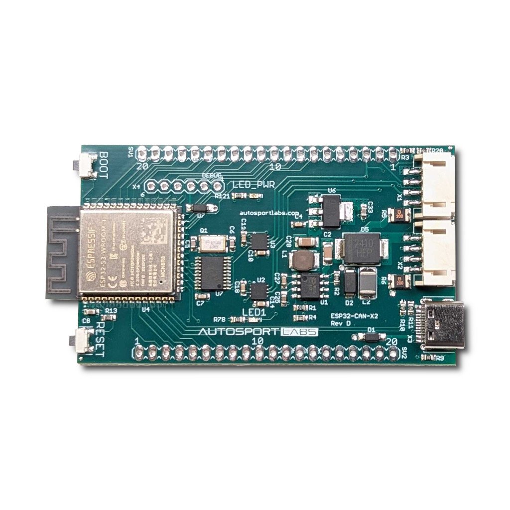
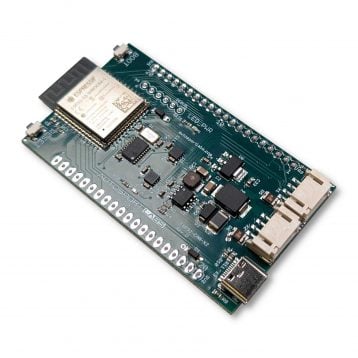
The Autosport Labs ESP32-CAN-X2 is a development board designed to make CAN bus communications easy for automotive and industrial applications.
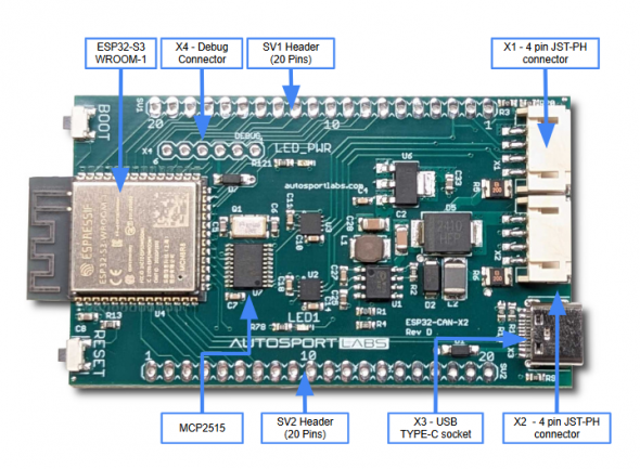
It features the ESP32-S3-WROOM-1-N8R8 using an Xtensa® 32-bit LX7 CPU operating at up to 240 MHz (8MB flash, 8MB PSRAM), dual CAN bus support, two CAN bus transceivers, and an automotive-grade power supply to safely integrate it into your car project.
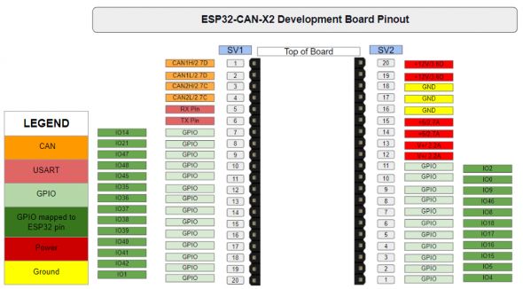
All IO pins are broken out to a breadboard-friendly layout so you can easily integrate it into bigger projects. A separate connector also provides power, ground, and dual CAN connections so you can quickly wire it into CAN networks.
Endless possibilities
- Create a button panel to broadcast messages to your PDM
- Trigger a relay (with additional support circuitry) via a CAN bus message
- Illuminate LEDs and indicators based on CAN bus messages
- Bridge two CAN bus networks with different baud rates
- Collect data from two different CAN bus networks with different baud rates
- Isolate traffic between CAN networks
- Create a “man in the middle” agent, which will help identify the source of CAN messages, helpful for CAN bus reverse-engineering efforts
- Sample Projects are available to get you started quickly
Features
- ESP32-S3-WROOM-1-N8R8 microcontroller powerful dual-core Xtensa LX6 CPU running at up to 240 MHz
- Automotive grade power supply: Ruggedized power supply up to 40v input, provides safety for automotive applications where damaging voltage surges and load dumps are common
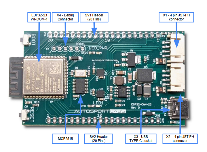
- Pin Headers: All available GPIO pins are broken out to the pin headers on the board for easy interfacing and programming. For details, please see our documentation
- USB-C port: A USB-C port supplies power for programming, flashing your code, communications using the USB 1.1 specification, and also provides JTAG debugging
- Boot Button: Firmware download button. Holding down **Boot** and then pressing **Reset** initiates Firmware Download mode for installing firmware
- Reset Button: Resets the device
- LED: User controllable LED; use it to indicate status or anything else you would like
- Power LED: Turns on when power is connected to the board
- Power / CAN headers: Dual 4 pin JST-PH header provides 12v (nominal) power, ground, and CAN connections for both CAN channels
- CAN termination jumpers: 2 CAN termination jumpers are provided, default enabled with 120 ohm termination
- Built-in CAN transceivers: Dual CAN transceivers are included on board
- 2nd CAN bus provided by MCP2515: while CAN1 uses the built in TWAI CAN compatible controller; CAN2 uses the on-board MCP2515 CAN bus controller
Full Documentation
We’ve created comprehensive documentation and starter code to get you going quickly.
Support via our community
We’re here to help and to hear about your ideas!
What’s included in the kit
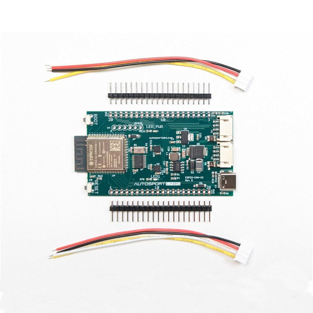
- ESP32-CAN-X2 development board
- Two 4 pin JST-PH pigtail for power, ground, and CAN connections
- Two 40 pin male headers for breadboard use

Reviews
There are no reviews yet.